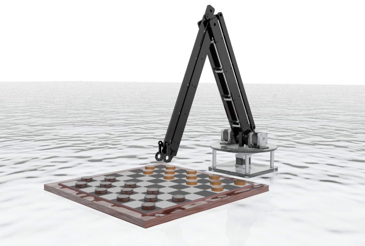
Parameter Analysis
The most important parameter for the robotic arm is its arm length. We need an appropriate arm length for the robot such that it can reach every piece on the game board. A typical size of the game board is 0.41 m x 0.41 m; therefore the robotic arm needs to at least extend its arm to its the length of the diagonal of the board, 0.41m*√2 = 0.57m. Our robotic arm consists of two links each with a length of 0.41 m; therefore its theoretical maximum extension is 0.82 m, which is more than enough for its purpose. Our other dimensions are made to accommodate this length. The size of our base is selected to fit the available stepper motors and the lazy susan is chosen to provide the rotation of our arm.
The shape of the robot largely caters to aesthetic appeal - it is simple, but effective. Our proof-of-concept prototype is made of wood, but it is extremely heavy (since the laser cut pieces are too flimsy on their own, the pieces are doubled up), and cannot handle buckling. We are deciding between acrylic or perforated aluminum for our final design, and will have to assess the two materials based on weight, cost, strength, and aesthetic appeal.
We also use inverse kinematics calculations to confirm that the robotic arm can reach every desired position on the game board. The following figure is a simplified diagram for the robotic arm in xy plane. This example is for a case with fewer linkages than ours, but the general equations still apply.

Simplified diagram of linkages for inverse kinematics calculations.

Links l1 and l2 are 0.41 m. We are interested in finding joint angles Ø1, Ø2, and Ø3 for moving the end of the robotic arm to desired location on the game board. To aid in solving this problem, an imaginary straight line that extends from the first joint to its last joint is defined as follows: B is the length of imaginary line, q1 is the angle between the x-axis and the imaginary line, and q2 is the interior angle between the imaginary line and link l1.
Equations and steps to find joint angles.
Our robot has one more joint on the base which rotates the whole arm in the z direction (into the plane of the paper). By running the above equations in the Arduino software, following the algorithm given in the final design below, we will confirm that the robotic arm can reach every desired location on the board with the designed length.
We also have stepper motors available for our use, but we have yet to perform rigorous torque calculations to ensure that the motors are strong enough to move the arms of our robot. The holding torque of the stepper motors are 4800 g-cm, so we are aiming to design the dimensions of the moment arm and the weight of the arm to fall within the motor specifications. Our motors are on the heavy-duty side, so they will most likely fall within our requirements.