Concept Description
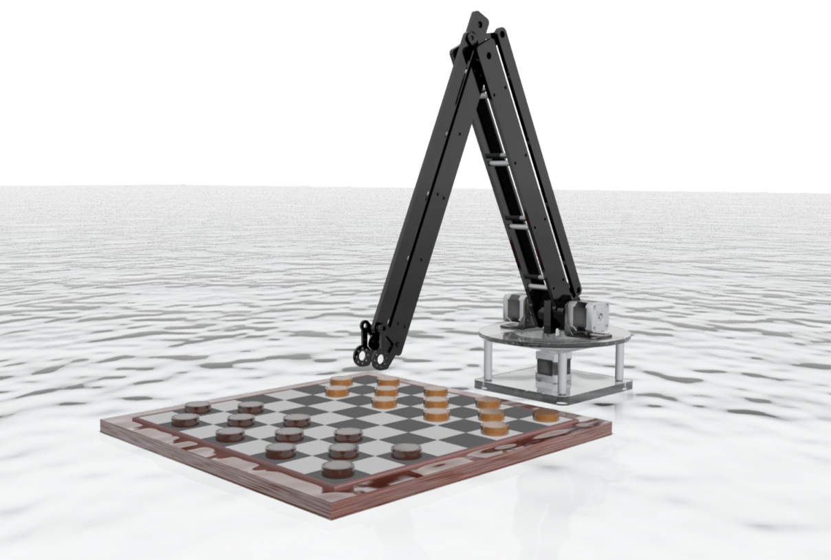
At a high level, our robotic arm is able to play checkers with another player by reading the game state and responding to his or her moves. An operational diagram is shown below to describe the various states involved with the control of the robotic arm. In this example, two robots play against each other and the diagram shows the workflow for a single robotic arm.

Overview of workflow for single robotic arm.

-
The first image shows the robot arm reading the game state and looking for changes.
-
Once the opponent has made a move, the robot arm calculates the next move it should make and takes the necessary steps to complete the move. This may require moving multiple pieces in checkers.
-
Once the robot arm has completed its moves, it returns to its home position and reads the game state, looking for changes before making its next move.
This project requires a variety of hardware and software. We can decompose the robotic arm into three subsystems: the mechanical plant, electronics, and software. Each subsystem acts as a black box with several input and outputs. These subsystems are shown in the diagram below and described in the following sections.
Dum-E subsystems.

Dum-E subsystems.
The electronics are responsible for reading the game state and actuating the robotic arm. It feeds the information from the sensors to the software, which then sends the appropriate commands to the electronic actuators.
The software reads the data from sensors and known geometries of the mechanical plant to create models of the arm and interpreted game state. Using simulation, the software can determine the best move and send commands to the electronic actuators to change the game state.