Final Design
Hardware


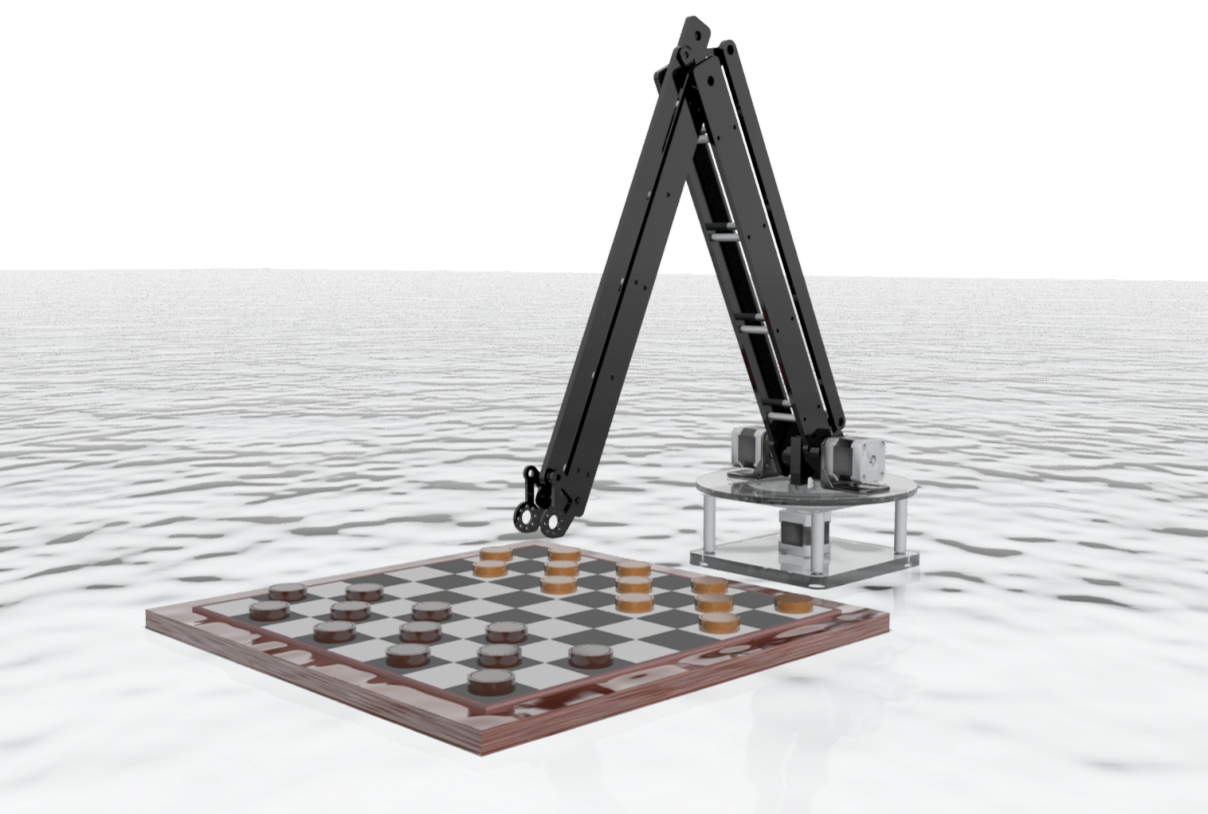
Renders of second prototype, Dum-E: Mark II.

Detail for dual shaft of robot arm.

Assembly drawing with relevant dimensions. The reach of the robot is approximately a hemisphere with a 32" radius.
The above figures show the updates in the hardware design of the robot arm. The basic concept is the same, but the base is updated to fit the electronics and incorporate the lazy susan.
The final hardware design involves planar machinery knowledge, and is notable for its simplicity and aesthetic value. It is the most convenient way of creating an arm that can be controlled with all of the motors (other than the small servo motor for the gripper) attached at the base to reduce arm weight. The design works in theory, and our proof-of-concept prototype created from laser cut wood show that the mechanism design is successful.
We considered a more complex design using gear trains or belts, but found that the simplicity of our design was ideal for manufacturing in limited time, and would also improve the accuracy and precision of the arm by eliminating error propagation that could come with creating gears or belts. We chose the dimensions for the design based on the necessary length of the arm and ease of manufacturing, and we scaled down our measurements from Design Review I based on feedback on the large size and weight. We redesigned the base in an effort to reduce the space taken up by the robot.
The cost of the robot is reasonable, since we have access to stepper motors, microcontrollers, and a camera, which are the most expensive features on our robot. Some parts will be purchased for convenience, such as a lazy susan and gripper, and stock parts have been bought and machined. The purchased items will be replaced with custom-made parts we have the time.

General bill of materials with in-house manufactured parts highlighted in green.
Software
With the design of the mechanical system completed, we now describe the framework for the control system. The robot runs a constant loop described by the following pseudo code in the algorithm below. The system checks for updates in the game state and performs moves accordingly.

Algorithm of the control system in pseudocode.
GetCurrentBoardState() returns a representation of the board state using a fixed camera and computer vision to detect where game pieces are located. CalculateNextMoves() returns a series of moves for the computer to perform based on optimization of a game tree. MakeMove(move) converts two board positions into xyz coordinate system positions to pick and place game pieces. It also contains the state machine and inverse kinematics necessary to convert xyz positions into steps for the motors.
Below is a sample output from the MakeMove function. Given a move from game position (0,0) to (1,1), the function returns the following commands to the three motor to pick the game piece with the end effector.

Commands to pick up the game piece at (0,0).

Detection of game pieces and conversion to computer represented game state.